Horizontal vs. Vertical Architecture: The Core Design Trade-off
Choosing between a horizontal and a vertical steering wheel is one of the most fundamental engineering decisions in AGV (Automated Guided Vehicle) design. This choice directly dictates chassis height, turning envelope, payload capacity, and overall vehicle layout.
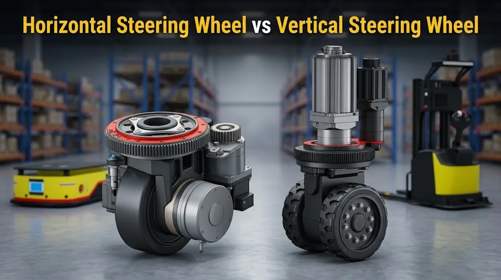
Space Allocation & Form Factor Trade-offs
Mounting orientation defines the physical footprint of the AGV chassis:
- Vertical Steering Wheels: Require substantial vertical clearance (150–300mm) inside the chassis, but maintain a tight horizontal turning radius. Ideal for narrow-aisle operation.
- Horizontal Steering Wheels: Significantly reduce overall vehicle height (50–150mm), enabling low-profile AMRs to drive under pallets, but demand larger horizontal turning clearance.
Load Distribution Mechanics
Drive assemblies act as primary load-bearing components. Chassis configuration determines how weight rests across multiple points. Mechanical engineers must calculate total static weight along with dynamic weight transfers during acceleration and braking. Overlooking dynamic load transfer can cause uneven tire wear or premature gear failure.
Horizontal Steering Wheel Assemblies: Technical Breakdown
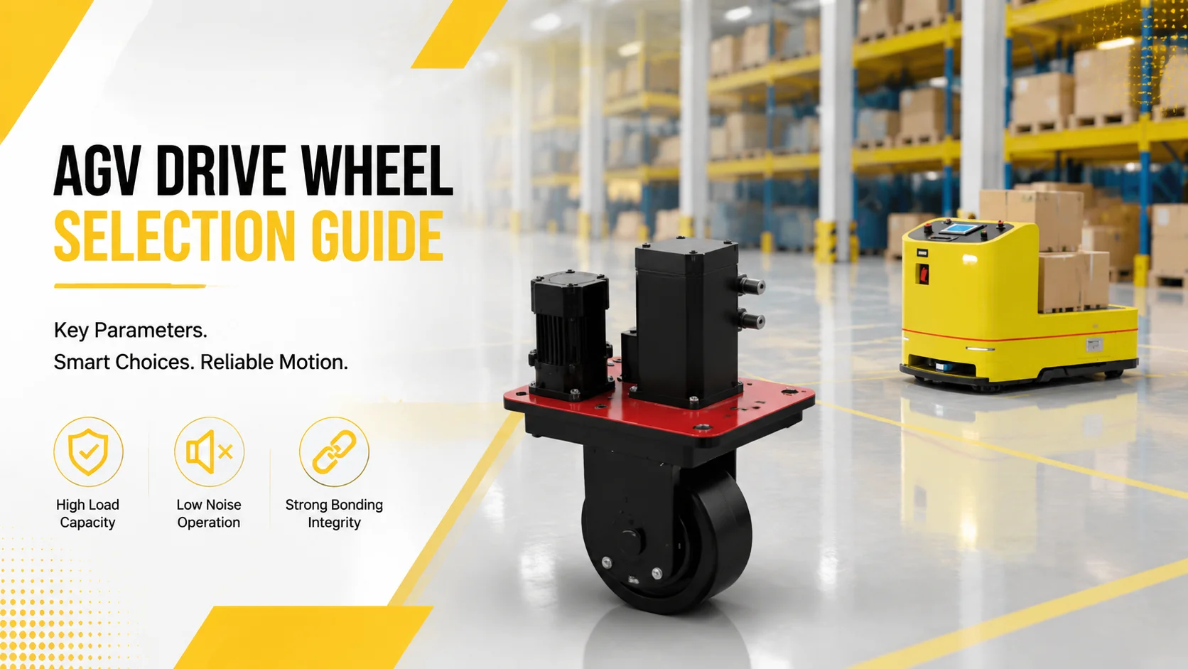
Horizontal steering wheels integrate drive motors, reduction gearboxes, and steering mechanisms into a single low-profile package. These components suit heavy transport applications where overall vehicle height is strictly restricted.
Internal Structure and Planetary Gear Transmissions
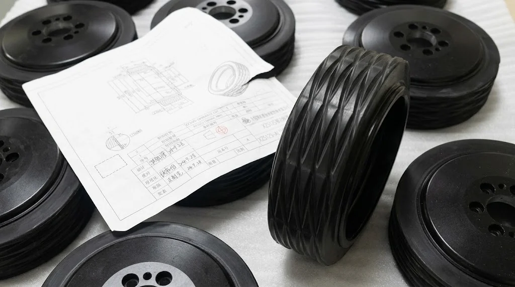
A three-phase AC motor typically powers the traction drive. A planetary gear reducer transmits torque efficiently while maintaining a compact form factor. Steering control relies on a permanent magnet DC motor paired with absolute encoders for accurate angle feedback. Polyurethane tread covers the wheel body to protect epoxy floors and maintain traction under heavy loads.
Key Specs and Load Handling Limits
Standard units feature motor ratings around 1.5 kW for driving and 200W for steering. Wheel diameters near 250mm support loads up to 2,000 kg per module. Advanced custom configurations utilize cast steel housings to handle loads up to 2.5 tons. Built-in limit switches monitor rotation angles to prevent mechanical binding or wiring stress.
Maintenance Practices for Maximum Uptime
Regular inspections ensure continuous operation in automated facilities:
- Check limit switch sensitivity every three months.
- Inspect polyurethane wheel treads for uneven wear patterns.
- Verify supply voltage stability to prevent motor overheating.
- Check planetary gearbox lubrication at scheduled intervals.
- Test encoder signal integrity across the control bus.
Vertical Drive Steering Wheels: Characteristics and Use Cases
Vertical steering wheels position the motor assembly perpendicularly above the tire axis. This design minimizes horizontal footprint while maintaining full steering flexibility.
Vertical Layout Advantages in Narrow Spaces
Vertical drive assemblies offer complete 360-degree rotation capability. Vehicles equipped with vertical wheels execute zero-radius turns and lateral maneuvers. High-strength hubs and composite tires distribute heavy loads evenly. Optional suspension frames absorb floor irregularities and protect sensitive electronics from vibrations.
Application Scenarios in High-Capacity Transport
Vertical steering setups excel in specialized material handling. They power automated forklifts, high-reach stackers, and heavy payload transporters. These units deliver precise millimeter-level positioning needed in automated warehouses and manufacturing plants.
Horizontal vs. Vertical Steering Wheels: Direct Comparison
Choosing the proper drive component requires balancing mechanical trade-offs against operational requirements.
| Feature Dimension | Horizontal Assembly | Vertical Assembly |
|---|---|---|
| Height Requirement | Low profile (50 – 150mm) | High profile (150 – 300mm) |
| Horizontal Footprint | Larger turning radius | Compact horizontal radius |
| Maintenance Access | Requires under-chassis access | Top-side or lateral access |
| Typical Target Vehicle | Low-profile AMRs, under-towing AGVs | Forklifts, heavy-duty stackers |
Engineer’s Selection Checklist
Evaluate system parameters before selecting a drive wheel architecture:
- Determine maximum floor clearance and overall chassis height limitations.
- Calculate total dynamic payload including safety margins.
- Evaluate floor conditions and select matching tread hardness.
- Verify controller compatibility for CANbus or RS485 communication.
- Assess environmental protection requirements (IP rating) for dusty or humid settings.
Frequently Asked Questions (FAQ)
Q: What is the main difference between horizontal and vertical AGV steering wheels?
A: Horizontal wheels position the motor parallel to the ground, creating a low-profile design ideal for under-towing AMRs. Vertical wheels place the motor vertically above the wheel, saving horizontal space and enabling 360-degree rotation in tight quarters.
Q: How do you calculate the load capacity for an AGV steering wheel?
A: Calculate capacity by dividing total gross vehicle weight by the number of load-bearing wheels, then multiply by a safety factor between 1.2 and 1.5. You must also account for dynamic weight shifts during braking and acceleration.
Q: What tread material is best for industrial AGV drive wheels?
A: Polyurethane is ideal for indoor industrial floors like epoxy. It offers high load capacity, excellent wear resistance, and floor protection. Rubber treads suit rougher outdoor surfaces where superior vibration dampening is required.