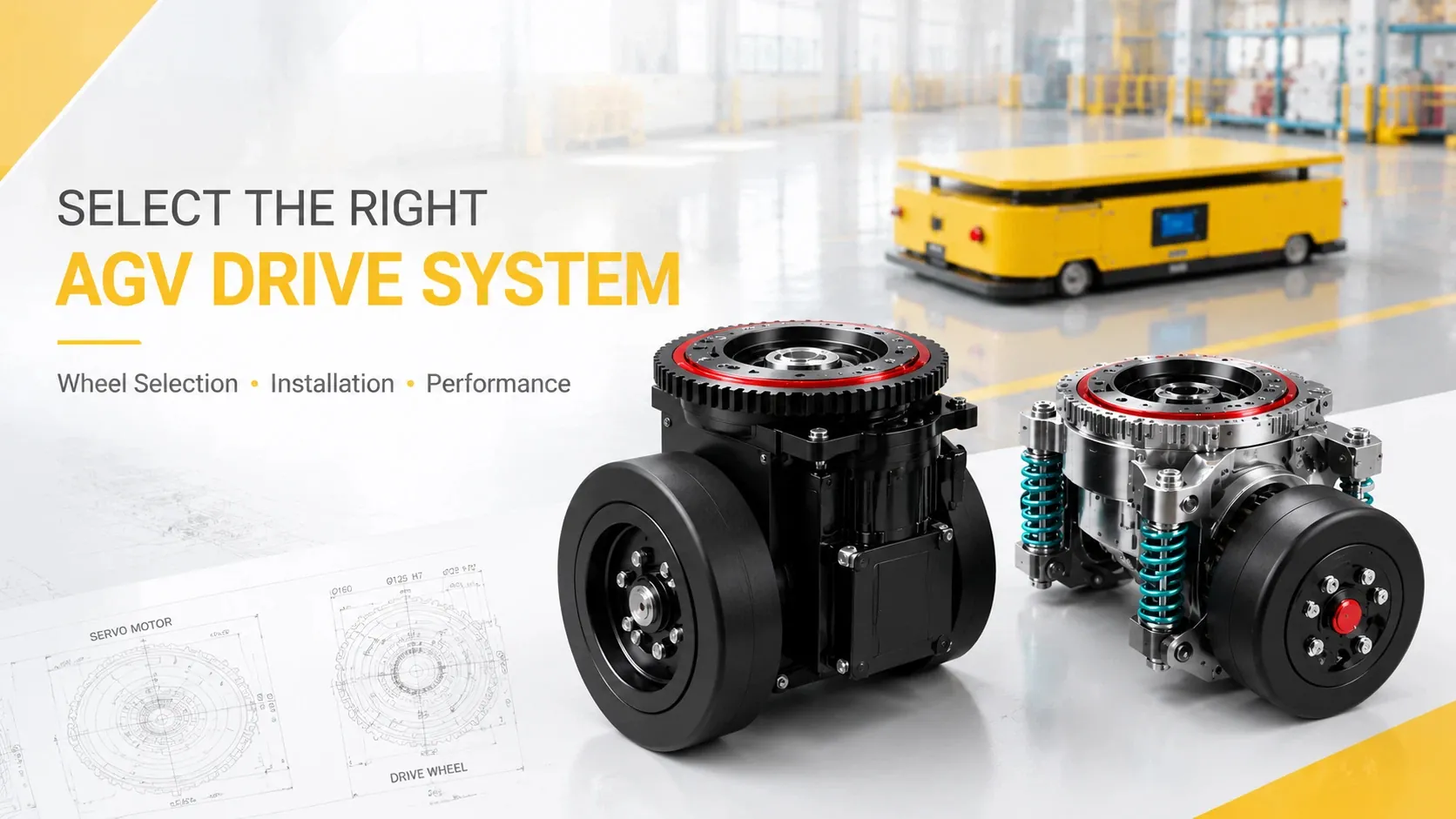
Why Simple Load Matching Fails in AGV Design
Factory automation requires reliable mobile robots. Many engineers face vehicle design failures during initial testing. They often look only at total load capacity when buying components. This simple mistake leads to weak motors and poor performance. It causes slow speeds, jerky movements, or component burnout. Houzai partners with Zhuolan to solve these common drive problems. We provide high-quality, cost-effective steering wheels and reducers. Our experienced team delivers one-stop technical support for your engineering needs.
Core Components of a Balanced Driving System
Selecting the right hardware requires a complete system match. You must balance the chassis layout, wheel load, travel speed, and motor power. Ignoring one factor ruins the whole system performance. Proper coordination ensures smooth acceleration and precise turning control. Our integrated solutions combine these factors to optimize your automated vehicle performance.
Engineering Principles for Traction Calculation
Three main forces affect your vehicle movement on the factory floor. Engineers must calculate these forces to size the drive components accurately.
First, calculate the total mass of the system. Combine the vehicle self-weight and the maximum cargo weight:
m = m_vehicle + m_load
Second, determine the rolling resistance force. This force depends on the floor material and wheel type:
F_f = m * g * f
In this formula, g ≈ 9.81 m/s². The variable f is the rolling friction coefficient. Polyurethane wheels on smooth concrete floors usually have a coefficient between 0.015 and 0.03.
Third, evaluate the acceleration resistance force. This relates to your target speed and acceleration time:
F_j = m * a
The variable α represents acceleration, calculated as target velocity divided by acceleration time.
Fourth, check the slope resistance force if your path includes inclines:
F_i = m * g *sinα
The variable α represents the slope angle in degrees.
Finally, add these values to find the total required traction force:
sum F = F_f + F_j + F_i
To find the force for a single wheel, divide the total traction by the number of driving wheels (N):
F_single = sum F\N
This single wheel force must not exceed the ground friction limit to avoid wheel slippage.
Next, calculate the required output torque using the wheel radius (R):
M_single = F_single* R
Now, estimate the required motor power. Introduce the travel speed (V) and the total transmission efficiency (η):
P = F_single* V/η
Mechanical transmission efficiency usually ranges from 0.7 to 0.85. Always add a safety margin between 1.2 and 1.5 when choosing the final motor model.
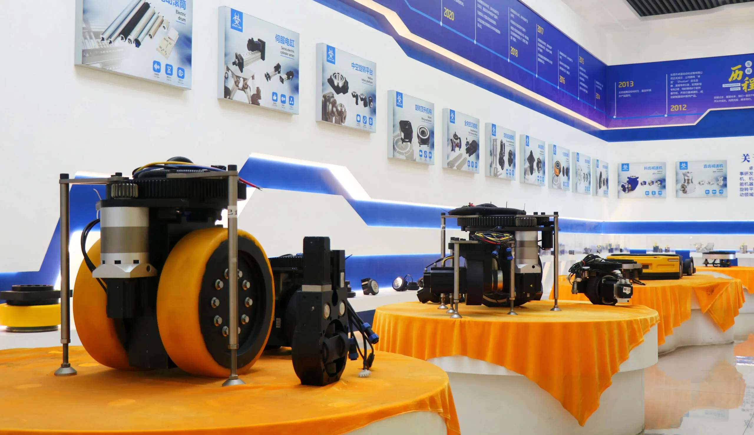
Seven Execution Steps for Component Selection
Follow this structured checklist to ensure a successful design process.
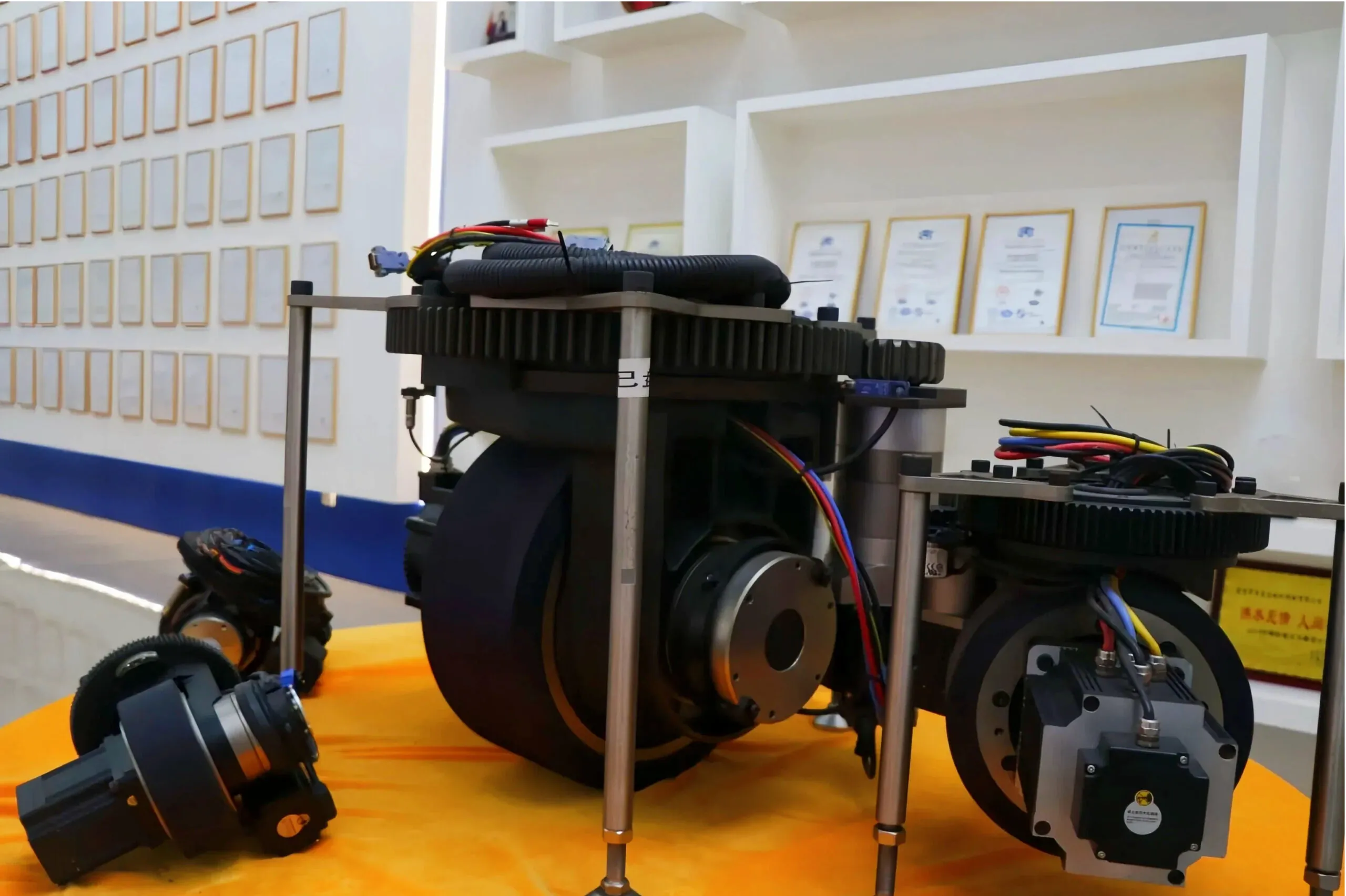
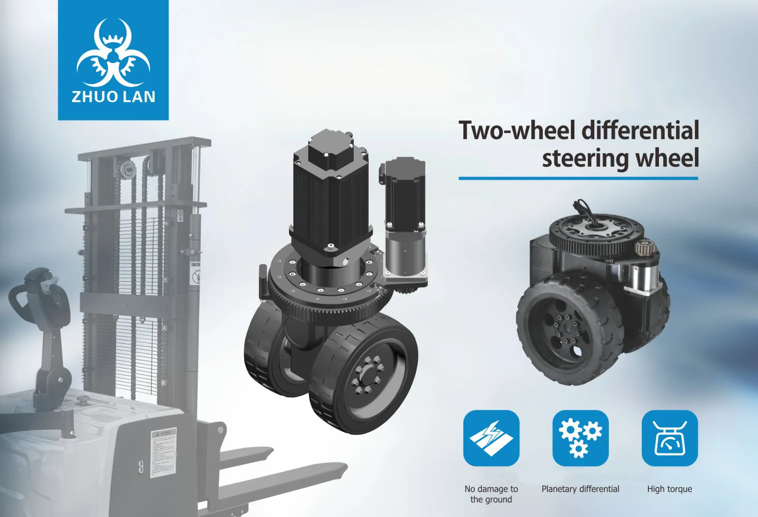
Step 1: Choose the vehicle chassis layout. Single steering wheel setups reduce costs for simple paths. Dual steering wheel configurations allow sideways crab movement and spinning. Quad wheel layouts provide maximum flexibility in extremely tight spaces.
Step 2: Estimate the maximum wheel pressure. Consider uneven floor contact and weight distribution. Ensure the static and dynamic ratings handle peak loads.
Step 3: Determine the wheel diameter. Small warehouse carts use 150 to 200 millimeter wheels. Medium vehicles use 200 to 300 millimeter wheels. Heavy industrial vehicles require 300 to 500 millimeter wheels.
Step 4: Compute the total driving resistance. Factor in the rolling friction, acceleration requirements, and any ramp slopes.
Step 5: Verify the motor power requirements. Ensure the rated motor power exceeds your calculated threshold under peak acceleration.
Step 6: Check the steering angle dynamics. Fast response times prevent sluggish turning behavior during transit operations.
Step 7: Match the physical and electronic interfaces. Verify mounting holes, brake systems, encoder types, and communication protocols.
Real World Application in Automation Projects
A manufacturing facility needed a mobile robot with a two-ton payload. The tight layout required frequent sideways moving patterns. Our team provided a dual steering wheel system. We utilized premium Zhuolan integrated reducers paired with high-performance servo motors. The vehicle achieved its top speed of 1.2 meters per second safely. It operates continuously without any motor overheating issues. This setup delivered excellent cost efficiency for the client.
Limitations of Standard Engineering Models
This mathematical model assumes clean and level factory floors. Rough, dusty, or wet surfaces change the friction coefficient drastically. Low friction reduces maximum towing capacity and causes wheel slippage. High precision paths may also require extra sensor calibration to fix steering drift.
Frequently Asked Questions for Drive Systems
Q: How do I choose between horizontal and vertical motor layouts?
A: Horizontal layouts keep the overall chassis height very low. They fit perfectly inside low-profile under-cart towing vehicles. Vertical layouts offer better clearance and superior environmental protection for harsh factory conditions.
Q: What steering angle is necessary for standard warehouse vehicles?
A: Most units use a steering range of ninety degrees. Continuous rotation models offer absolute freedom of movement. These allow the vehicle to change direction without stopping.
Q: How does AGV drive wheel calculation prevent motor failure?
A: Proper AGV drive wheel calculation ensures the motor handles peak loads. Underpowered motors overheat quickly when facing sudden floor slopes. Accurate math prevents these costly hardware failures entirely.
Q: How does floor condition impact wheel selection?
A: Floor conditions change the friction limits of polyurethane wheels. Wet or greasy floors lower traction. You must adjust your acceleration targets to prevent wheel spin in these environments.