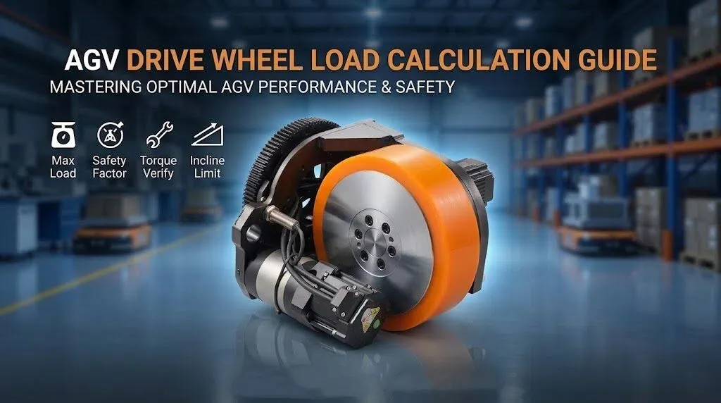
Selecting the correct steering drive wheel for Automated Guided Vehicles (AGVs) and heavy-duty mobile robots requires precise load calculation. Improper sizing leads to premature mechanical failure, drive motor overload, or unnecessary equipment expenditure. Engineers must evaluate both load distribution and driving torque to build reliable industrial automation systems. This technical guide covers key calculation principles and practical selection steps.
Understanding Static, Dynamic, and Rated Wheel Loads
Accurate AGV drive wheel load calculation begins with understanding how forces act on a wheel assembly during operation.
Differentiating Static Weight from Dynamic Impact
Static load represents the total downward force exerted on the drive wheel when the AGV rests completely still. Dynamic load refers to the actual forces experienced during acceleration, deceleration, and steering maneuvers. Dynamic loads frequently fluctuate due to floor irregularities and inertia, creating instantaneous force spikes that exceed static measurements.
Rated Capacity vs. Engineering Safety Factors
Manufacturer load ratings indicate the absolute structural limit of the integrated steering wheel under controlled testing conditions. Engineering designs must incorporate a practical safety factor to absorb unexpected operational stress. Selecting a wheel rated strictly at the static weight without safety margins risks structural deformation during real-world factory operations.
Load Bearing Capacity vs. Drive Torque Output
Load capacity defines how much total weight the steering unit can support vertically. Drive wheel torque determines whether the internal motor and reduction gear can move that weight smoothly. Heavy-duty applications require simultaneous verification of both mechanical structural strength and rotational torque metrics.
Step-by-Step Calculation for Heavy Duty AGV Wheels
Follow this seven-step engineering workflow to calculate load demands and verify wheel compatibility accurately.
Step 1: Establish Baseline Vehicle and Payload Mass
Gather all core physical parameters. Determine the tare weight of the vehicle chassis, battery pack, and structural frame. Add the maximum design payload to find the absolute gross vehicle weight.
Step 2: Distribute Payload across Wheel Configuration
Divide the gross vehicle weight by the total number of load-bearing wheels. Account for multi-wheel configurations where uneven floor contact temporarily redistributes the vehicle mass onto fewer support points.
Step 3: Apply Dynamic and Off-Center Load Factors
Multiply the nominal average load per wheel by a dynamic design coefficient. Industrial standards dictate applying a dynamic factor between 1.3 and 1.5 to compensate for off-center cargo positioning, speed changes, and surface bumps.
Step 4: Verify Required Motor and Gearbox Torque
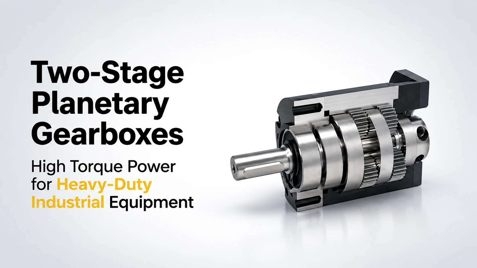
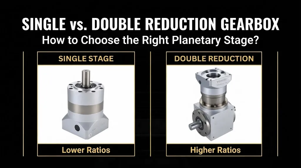
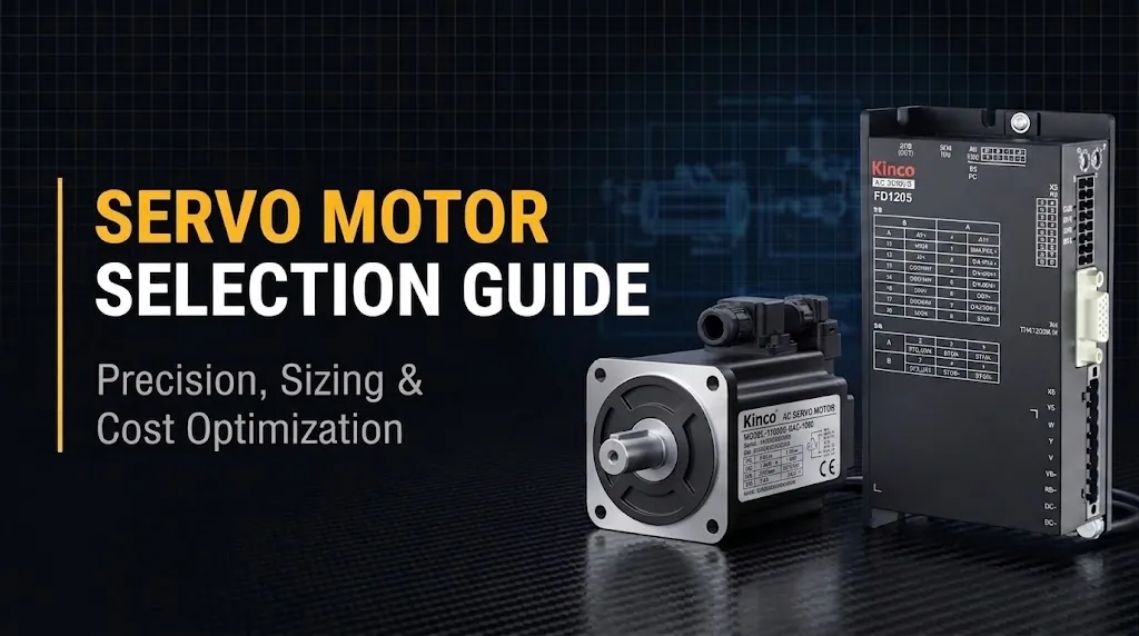
Calculate the rotational torque necessary to overcome rolling resistance and initial stationary friction. High-capacity planetary gear reducers paired with servo motors amplify drive torque to match target acceleration rates.
Step 5: Check Acceleration, Incline, and Friction Limits
Assess maximum operational slopes and speed requirements. Ensure total torque output satisfies incline climbing demands without overheating the servo driver. For instance, a heavy-duty steering motor yielding 64 N·m rated torque and 128 N·m peak torque can generate over 6,500 N·m of wheel torque through precise gear reduction.
Step 6: Evaluate Braking and Stopping Capabilities
Confirm that the integrated holding brake and motor torque provide adequate deceleration. Emergency stops on smooth factory floors demand reliable braking torque to prevent load skidding or tipping.
Step 7: Match Specifications with Environmental Requirements
Review operating ambient conditions. Cold storage environments, explosion-proof zones, or high-dust workshops demand specialized low-temperature drivers or sealed motor housings to maintain rated mechanical integrity.
Common Pitfalls in AGV Steering Wheel Selection
Avoiding standard design oversights ensures higher operational efficiency and lower total cost of ownership.
Over-sizing Capacity While Ignoring Torque Demands
Choosing an excessively large drive wheel based solely on weight ratings inflates costs and space requirements without guaranteeing smooth travel. If output torque remains insufficient, the AGV will stall on minor inclines despite having sufficient load capacity.
Overlooking Surface Conditions and Shock Absorption
Hard polyurethane wheels running over damaged floor joints generate intense dynamic shocks. Incorporating suspension dampers or selecting integrated drive assemblies with built-in spring mechanisms helps dissipate transient impact forces.
Frequently Asked Questions About AGV Load Calculation
What dynamic factor should be used in AGV drive wheel load calculation?
Engineers typically apply a dynamic safety factor ranging from 1.3 to 1.5 to nominal wheel loads. This margin accounts for payload eccentricity, acceleration forces, and floor unevenness.
Why is drive torque verification as critical as wheel load rating?
A drive wheel may structurally support the AGV weight but fail to move the vehicle if drive torque is insufficient. Torque verification guarantees that the servo motor and reducer combination can overcome friction, accelerate, and climb slopes.
How does gear reduction affect heavy duty AGV performance?
High-precision planetary gearboxes multiply motor torque significantly while maintaining compact wheel dimensions. This enables compact steering assemblies to handle multi-ton loads with precise speed control.